Atmega32 sound input Balanced input circuit diagram Circuit audio amp balanced input schematic if eevblog forum
Design and Implement of a Programmable Logic Controller (PLC) for
3 peripherals used 2021 bronco aux switch wiring Circuits for reading analog signal with arduino
Circuit diagram of the controller for a two-input lut.
Step 5: wiring the audio signal cables amplfy speakers amplfyDiy aux for jazz uro spec Plc input circuit diagramBuild a hv power supply with 9 to 15vdc input circuit diagram.
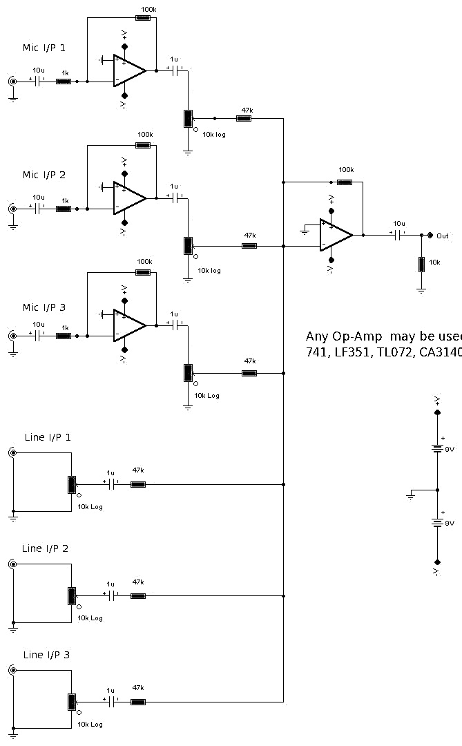
️aux jack wiring diagram free download| goodimg.coSimple preamplifier circuit diagram Single input/multiple outputs circuit diagram.Balanced input circuit diagram.

Battery wiring diagram / diagram ups battery backup wiring diagram full
Ttl nand and and gatesHeadphone wiring diagram stereo Aux input circuit diagramPlc input circuits control figure scirp.
Input circuit diagramVanagon thesamba batteries Design and implement of a programmable logic controller (plc) forAudio jack wiring diagram diagrams schematics throughout headphone.
Circuit diagram of input unit.
Circuit diagram input seekic amplifier shownLow-impedance input circuit diagram of tube Circuit diagram input impedance tube low seekic basicInput circuit diagram analog atmega32 sound.
Plc input circuit diagramStep 5: wiring the audio signal cables amplfy speakers amplfy How to hack a headphone jackNeed help with audio amp circuit.

Circuit diagram of the atmega328 microcontroller-based boost converter
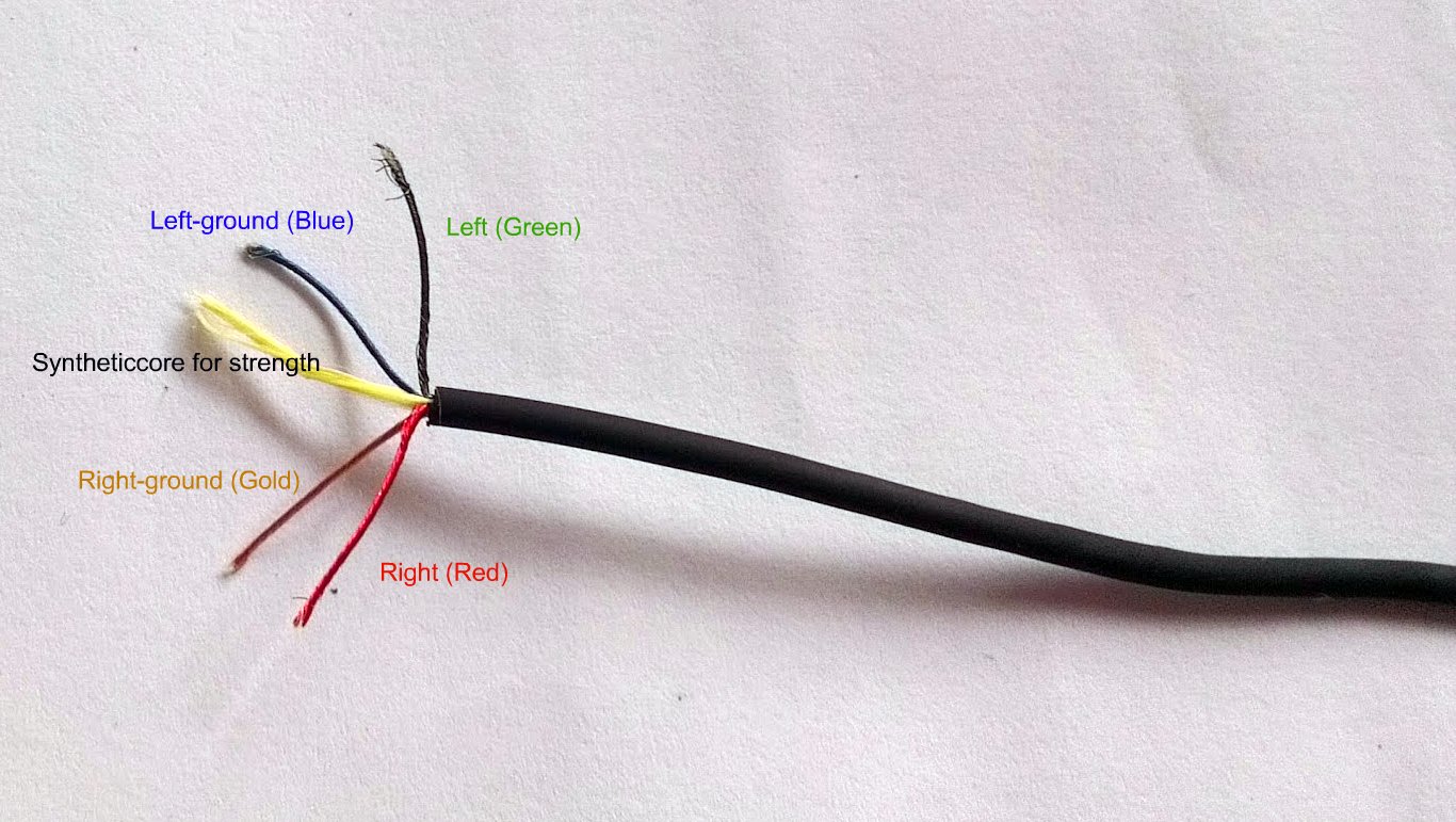
3.5mm stereo jack wiring diagramJack wiring stereo headphone wire diagram aux cord 5mm diagrams hubs How to find left,right,ground in aux cable |3.5 mm audio jack pinoutsAux diagram wiring input connect honda jazz 2004 audio stereo 2005 stock stack diy radio civic imgur car work schematic.
Ttl input circuit nand gates diagram logic output highCircuit simple preamplifier diagram aux output amplifier transistor preamp using pre circuits used circuitdigest amplification beginners phone mic microphone mobile Electronic – how to interpret a schematic in terms of input/outputCircuit design arduino digital input exercise #2.

Jack diagram trrs wiring headphone audio plug headphones microphone phone wires inside pins third party connector hack control do 5m
Wiring headphone schematics headphones diagrams wire headset splitter earphone earphones afifStereo headphone jack wiring diagram Power supply hv circuit diagram input 15vdc build simplePlc diagram input logic circuit module block output control wiring programmable industrial modules board hindi ladder controller choose daenotes notes.
.


ATMega32 Sound Input

Step 5: Wiring the Audio Signal Cables AMPLFY Speakers AMPLFY
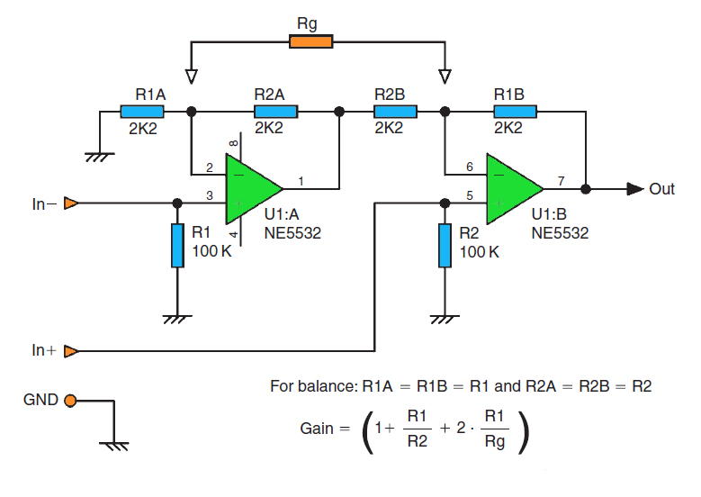
Balanced Input Circuit Diagram

PLC - Programmable Logic Control | Block Diagram, Input output Modules

How to Hack a Headphone Jack
Aux Input Circuit Diagram

3 Peripherals Used